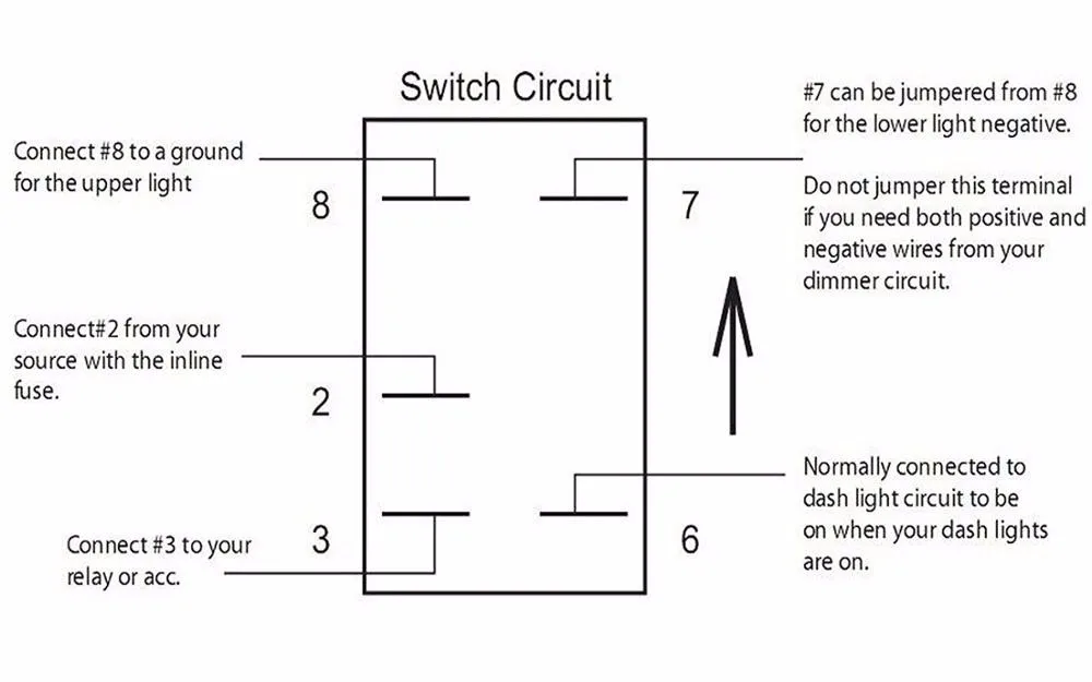
4 Pin On Off Switch Wiring Diagram
Click here for 727 to 46rh swap wiring diagram pa 727518. But, since the pin 4 of cd4017 is connected to the reset pin, all the outputs will become low and hence the relay will be turned off, which in turn switches off the light.
Then please make sure that your notch filter is turned off.

4 pin on off switch wiring diagram. 3 pin on/off rocker switch with red indicator light when truing on, easy to turn on or off, has been passed test of 5,000 times pressing. C pin and one of two remaining pins. 3 pin xlr wiring standard.
Turn the ignition switch to run and observe the indicator lights. So, considering all the possibilities, the light is on in two cases: Pin 3 (sda0) and pin 5 (scl0) are preset to be used as an i²c interface.
Dining table (extendable) + 4 chairs. And by energizing the relay, the power is cut off. Although the limit switch has 3 pins, a normal application usually uses only two pins:
The filling must follow the scheme as follows: Connect a test lead between terminal number 5 (grey wire) and ground. The sensing element wires go to the pcm, in which one wire is signal ground and the second wire is signal voltage.
They incorporate both normally open and normally closed connect pins. So there are 1.8 kohm pulls up resistors on the board for these pins. The cable can be attached in many different ways.
Using the test box v.a.g 1598/18 the wiring can be checked according to the wiring diagram. The first switch com terminal connected to phase and second switch com terminal is connected to one end of the bulb and the other end of the bulb is connected to neutral ac supply. A 4 wire oxygen sensor wiring diagram is also called a universal o2 sensor wiring diagram.
Com of switch 1 is connected to l1 and com of switch is connected to l2. Package include:1 x wiring harness kit, 1 x instructions. The breakaway switch cable needs to be secured to the vehicle bumper or frame.
Route the pin through a tow hook, then through the cable loop. Pin #4 is always the audio output. The two most common methods are:
Selling because we are moving. Accordingly, there are four ways to use limit switch. Ford 8n 12 volt conversion wiring diagram — untpikapps www.untpikapps.com.
(the rear view is the end you solder from) here are the connections on each pin: 5 pin relay 2 pins (85 & 86) are required by the 5 pin relay to power the coil, and 3 pins are used (30, 87 & 87a) that are supposed to shift power among two circuits. Now at 52 mph when you step on the gas the transmission will shift back to third gear.
The above diagram shows you the pin numbering for both male and female xlr connectors, from the front and the rear view. Extendable dining table in glass with 4 white chairs 180 → 240 x 100 x 75 cm in excellent condition. Package included:1 x wiring harness full wiring kit,1 x diagram.
This indicates the 4×4 hi lights/dash lights are good. A relay is an electrical switch used to control a high amount of current by using a little amount of current. Wiring diagram gauge volt wire amp.
A 4 pin relay controls a single circuit, whereas a 5 pin relay switches power between two circuits. Ⅳ 4 pin relay wiring diagram vs 5 pin relay wiring diagram 4.1 the main difference between 4 or 5 pin relays. This action will once again cause the same action i.e.
This indicates the 4×4 lo switch/dash lights are good. For a normally closed, when the coil is initiated, it will shut the power off for a circuit. Bought 15th october 2019 at conforma, guaranteed for 2 years.
It is important to install the dse 7320 mkii on the generator. Diagrams 8n shay ammeter harness 1494 schematics distributor 2020cadillac chev untpikapps stromlaufplan firing alternator schaltplan [hy_8298] 12 volt amp gauge wiring diagram free diagram inst.unec.hendil.mohammedshrine.org. Run a wire from the front pin on the transmission connector to the 44 psi oil pressure switch and a second wire from the rear pin on the transmission connector to the 52 psi oil pressure switch.
The 4×4 light in the instrument panel and 4×4 light on the switch should illuminate. The below is the wiring table for limit switch and the reading state on arduino in all four ways: 2 pins (85 & 86) control the coil and 2 pins (30 & 87) switch power on a single circuit in a 4 pin relay.
Two way switch front and back view. Fuel & output bank (flexible with can). 3 pin xlr connectors are standard amongst line level and mic level audio applications.
Alternative method of two way switch wiring. Route the pin through the safety chain loops on the hitch or bumper, then through the cable loop. With 2 sets of light output connectors for dual lighting fixtures less than 180w, the connection is more stable.
The vehicle wirings are of a normal gauge that can not carry a huge amount of current. It has just 2 prongs: Deep sea electronics 7320 wiring diagram & 8610, 6020, 6120, 4520 basic deep sea wiring diagram.
Com of switch 1 is connected to l2 and com of switch is connected to l1. To turn off the light, we can toggle either switch 1 or switch 2 as any toggling action will break the flow of current to the light.
Quality Assurance Momentary Carling Lighted 5 Terminals 5 Pin Rocker Switch Wiring Diagram Buy
Push Button Ignition Panel 4 Duckbill Switches MGI SpeedWare
Repair Guides Electronic Engine Controls Camshaft Position (cmp) Sensor
Shop for 3Pin SPDT Toggle Switches MGI SpeedWare