Vickers Solenoid Valve Wiring Diagram
Single solenoid valves, solenoid at port a end single solenoid valves, solenoid at port b end pt ab sol. Two stage directional valves are pilot pressure operated.
18 Lovely Hydraulic Solenoid Valve Wiring
From when the pilot valve solenoid is energized to the time the main stage spool shifts to its full stroke.

Vickers solenoid valve wiring diagram. Solenoid valve and proportional valve coils and electronic controls for proportional valves. Single solenoid models:1,6 kg (3.5 lb) double solenoid models: Nameplate (see table) 890332 gasket 890333 cover 890330 strap 36212 screw (2 req'd) 473710 screw (2 req'd) 576915 screw (ground) 890341 terminal box (w builds) 890342 terminal box (j.
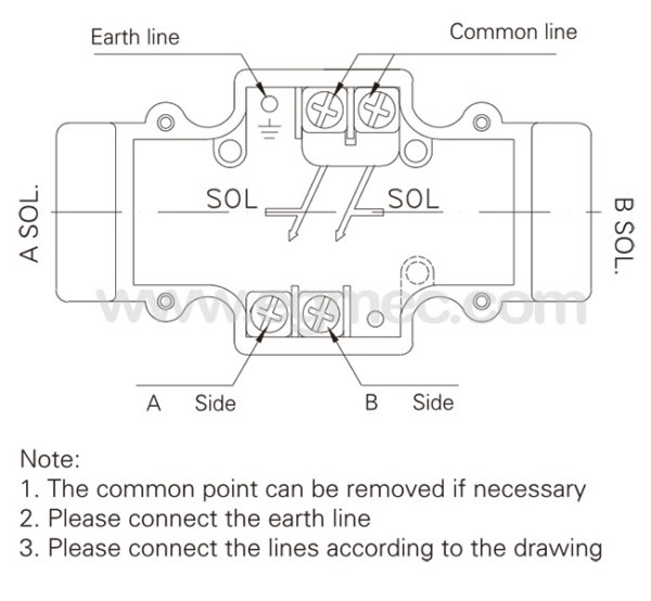
Solenoid models, pilot valve & cover s/a are rotated 90_ clockwise from body. Single solenoid valves, solenoid at "a" port end. Electromagnetic compatibility (emc) screened cables should be used and particular attention paid to the grounding of the screens as shown in the above diagrams.
For actual maximum flow refer Connections to the valve are made in the wiring housing, and a ground terminal is provided. Type "78c" is the same as type "7" except solenoid is assembled on opposite end (do not reverse solenoid on "78b" models) and a different diagram plate is used.
Vickers®, one of the most experienced and respected names in hydraulics, became part of eaton in 1999. Vickers solenoid force normal solenoid force range on the market vickers spring force normal spring. Class n, 200°c (392°f) nema pub.
When a pilot valve solenoid is energized (activated), the pilot spool moves and fluid is diverted to the mainstage; Uses vickers dg4v3(s) pilot valve for exceptional responsiveness, durability,. Solenoid valve (solenoid "b" only) solenoid "a" for "v" version, throttle valve c spring centered, dual solenoid, direction valve
Type "68c/b" models are used as pilots for spring centered two stage valves with "4" or "8" type spools only. Single solenoid valves, solenoid at "b" port end. 1) it is important to.
Figures 4 and 5 show the recommended electrical connection scheme for a kb type valve and the following information should be used when wiring the valves. When solenoid "b" is energized, flow is always p b. Vickers solenoid valves are offered with the widest choice of flow paths and position options to satisfy most requirements.
Refer to pilot valve drawing for. 0c wf dg4v3s0cmftwlb560 wiring box, spring centered, two solenoids, light kit, 120 vac, 50/60 hz 7c wf dg4v3s7cmftwlb560 wiring box, spring centered, two solenoids, light kit, 120 vac, 50/60 hz note: The kdg is a proportional directional valve with two solenoids.
See page 7 for spool function chart. A two stage valve is constructed by combining a pilot valve and a larger main stage valve into one assembly.
30 Yuken Directional Valve Wiring Diagram Wiring Diagram
Eaton Vickers DG4V3(S) Series Valve Part 508172 Hydraulic
YUKEN Directional Control Valves DSHGS04, 06

Solenoid For Sprinkler Valve Wiring Diagram Wiring

Samson Steel Type Pneumatic Solenoid Valve For Controlling
Patent US20110283693 Regenerative Hydraulic Circuit For
Yuken Hydraulic Solenoid Operated Directional Valve
Hydraulic Solenoid Valve Manifold Normal Flow D03NFx2

12 Volt Eton Solenoid Wiring Diagram Wiring Diagram Schemas

Electric Solenoid Valve Wiring Diagram topcunts

86514802 Solenoid Coil Top Kit Emerson Ag and Industrial

Yuken Directional Valve Wiring Diagram

Wiring Diagram For Hydraulic Solenoid PALOTAKENTANG

Yuken Directional Valve Wiring Diagram
YUKEN Directional Control Valves DSG03

30 Yuken Directional Valve Wiring Diagram Wiring Diagram


